
Four decisions in coil design fix the product’s behaviour: the geometry, the ferrite and shielding stack, the alignment tolerance and the thermal path. Each is a mechanical decision with an electrical consequence, and each is cheaper to take before the tooling than after it.
Wireless charging coil design: the four decisions
Geometry and turns, the ferrite and shielding stack, the alignment tolerance, and the thermal path.
The decisions interact: a thinner stack saves volume and raises the resistance, a larger coil widens the coupling but takes space, and a thicker ferrite improves the field shaping while adding height. Reading them together is what makes the design a set of trade-offs rather than a component purchase.
The measurements that close the decisions are the same four that a buyer should ask for: delivered power at the alignment position, temperature rise at full load, the alignment tolerance and the field behaviour that the foreign object function depends on.
Decision 1: geometry and turns
The coil’s outer diameter and turn count set the coupling and the resistance.
A larger coil couples better with a wider range of receiving coils and takes more space; more turns raise the induced voltage and the resistance; a thinner wire fits the stack and carries more loss. The design has to be matched to the receiving side, because the coupling depends on the relationship between the two coils rather than on the transmitter alone. The output of this decision is a geometry with a stated delivered power against a named reference device.
Decision 2: the ferrite and shielding stack
Three layers, each with a job.
The ferrite shapes the field towards the receiving coil, the shielding keeps the field away from the electronics behind the coil, and the adhesive and carrier hold the stack together through the assembly process and the product’s life. Thickness is the currency: less ferrite means less shaping and less protection, and the field that is not shaped is the field that heats something else. The stack is also where the thermal path is decided, because the coil and the ferrite both sit against the surface the phone rests on.
Decision 3: the alignment tolerance
How far the phone can be placed off centre before the delivered power falls.
The tolerance is set by the coil geometry, the magnet ring where one is used, and the mechanics that position the phone. It should be stated as a distance rather than as a description, because the customer experiences it as a place where the phone stops charging quickly. A magnetic reference converts the tolerance into a fixed position; a coil array widens it; a locating feature depends on the user.
Decision 4: the thermal path
The coil stack is a thermal component as well as a magnetic one.
The losses in the coil, the ferrite and the switching stage all leave through the same housing, and the stack’s thickness and materials belong to that path. The measurement is the temperature rise at full power in the shipping enclosure at a stated ambient, with the derating threshold recorded if the design reduces power above a temperature. A coil that measures well on a bench can fail this measurement inside a thin enclosure.
| Decision | What it sets | Measurement | What it costs later |
|---|---|---|---|
| Geometry and turns | Coupling and resistance | Delivered power with a reference device | A new coil and a new fixture |
| Ferrite and shielding | Field shaping and protection | Field behaviour and thermal result | A new stack and a new tool |
| Alignment tolerance | The usable placement area | Delivered power across the surface | A new mechanics revision |
| Thermal path | How the losses leave the product | Temperature rise at full load | A new enclosure |
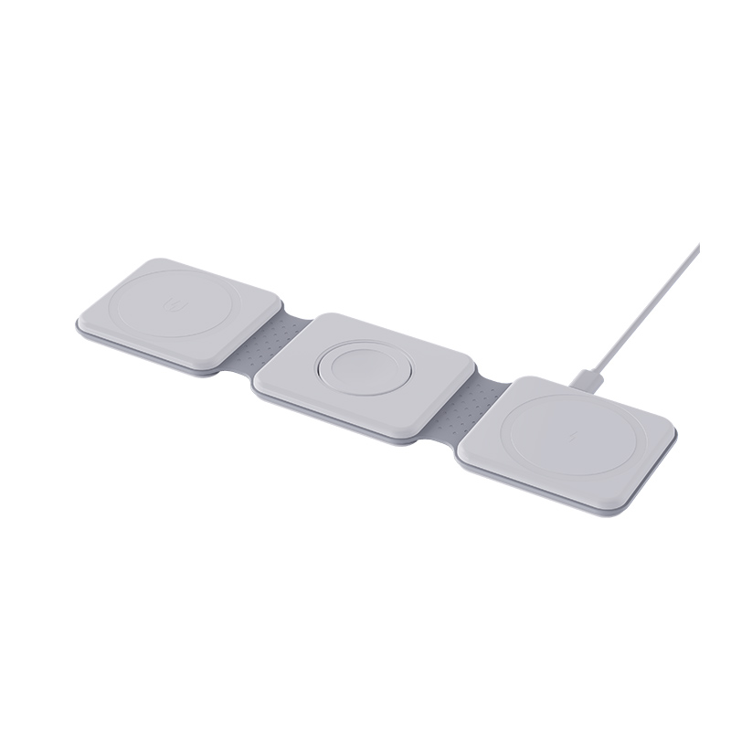
How the coil interacts with the rest of the product
Three interactions that decide whether the design works in the enclosure.
The magnet array, where one is used, has to be concentric with the coil and its position is fixed by the same fixture; the electronics behind the coil are protected by the shielding, and the shield has to be positioned relative to both; and the surface the phone rests on sets the gap and the thermal path. The three are decided in one mechanical revision, which is why the coil decision is a mechanical project.
What to verify on production units
Three measurements, and the first of them is the one that matters most.
Delivered power at the alignment position with a reference receiver, measured per unit or per lot; concentricity between the coil and any magnet array, measured on finished units; and the temperature rise on a sample per build. Together they show whether the design is holding, and they are the evidence a buyer asks for when a batch behaves differently from the sample.
Where coil designs go wrong
Three patterns, and each is visible in the first production batch.
A geometry matched to a prototype receiving coil and not to the device list; a stack that fits the enclosure and leaves no thermal path; and an alignment tolerance stated as a description rather than a distance. Each is a specification gap, and each produces the same complaint: the product charges slowly in some positions and not others.
FAQ
Does a bigger coil always charge faster?
A larger coil couples better with a wider range of receiving coils, and it also takes more space and can add resistance. The useful comparison is the delivered power against the device list, measured at the alignment position. A larger coil couples better with a wider range of receiving coils and also takes more space, so the comparison is delivered power against the device list.
What does the ferrite actually do?
It shapes the field towards the receiving coil and improves the coupling, while the shielding behind it keeps the field away from the electronics. Both functions depend on thickness, which is why the stack is a design decision rather than a material choice. It shapes the field towards the receiving coil while the shielding behind it keeps the field away from the electronics, and both depend on thickness.
How should alignment tolerance be specified?
As a distance over which the delivered power stays within a stated limit, with the reference device named. A description such as wide charging area cannot be measured or compared. Specify a distance over which the delivered power stays within a stated limit with the reference device named, because a description such as wide charging area cannot be measured or compared between designs.
Why does the product get warm?
Because the coupling, conversion and coil losses all become heat inside the same enclosure that carries the stack. The thermal path and the derating threshold are the design’s answer, and both are measured at full power in the shipping assembly. The coupling, conversion and coil losses all become heat inside the same enclosure that carries the stack, so the thermal path and the derating threshold are the answer.
Next step
Send the device list, the form factor and the target power to Wecent Group through the contact page. The reply states the coil geometry, the stack, the alignment tolerance with its distance and the thermal result at full power in the enclosure. Related reading: wireless charger applications, OEM and ODM charger manufacturing and charger quality control. External references: WPC knowledge base, Wireless Power Consortium, IEC standards, IEC Webstore, UL standards and certification and TUV testing services.
{“@context”:”https://schema.org”,”@type”:”FAQPage”,”mainEntity”:[{“@type”:”Question”,”name”:”Does a bigger coil always charge faster?”,”acceptedAnswer”:{“@type”:”Answer”,”text”:”A larger coil couples better with a wider range of receiving coils, and it also takes more space and can add resistance. The useful comparison is the delivered power against the device list, measured at the alignment position.”}},{“@type”:”Question”,”name”:”What does the ferrite actually do?”,”acceptedAnswer”:{“@type”:”Answer”,”text”:”It shapes the field towards the receiving coil and improves the coupling, while the shielding behind it keeps the field away from the electronics. Both functions depend on thickness, which is why the stack is a design decision rather than a material choice.”}},{“@type”:”Question”,”name”:”How should alignment tolerance be specified?”,”acceptedAnswer”:{“@type”:”Answer”,”text”:”As a distance over which the delivered power stays within a stated limit, with the reference device named. A description such as wide charging area cannot be measured or compared.”}},{“@type”:”Question”,”name”:”Why does the product get warm?”,”acceptedAnswer”:{“@type”:”Answer”,”text”:”Because the coupling, conversion and coil losses all become heat inside the same enclosure that carries the stack. The thermal path and the derating threshold are the design’s answer, and both are measured at full power in the shipping assembly.”}}]}