
A charger went to tooling with a two-piece enclosure and came back with a draft angle that could not be moulded at the wall thickness specified. The design was correct on paper; the two numbers had never been checked against each other. Design for manufacturing is a set of checks taken before the die is cut rather than a review held after it.
Charger design for manufacturing: what it changes
Four decisions, and each one is cheaper before tooling than after it.
The architecture, the enclosure and its tooling, the assembly method and the test points. A programme that settles them at the concept stage pays for them once; a programme that discovers them at the pilot run pays for them in a second die.
The enclosure that could not be moulded
Two numbers that were never compared.
The wall thickness was set for the thermal target and the draft angle was set for the appearance, and the combination is not mouldable in the material chosen. The correction was small in millimetres and large in schedule, because the die had already been cut by the time the moulding trial reported it.
Decision one: the architecture
It decides how many assemblies the line has to handle.
A single-board design with an integrated power stage has fewer parts and a simpler test; a modular design with a separate daughter board is easier to vary across markets and adds a connector to the process. The choice follows the number of variants the programme expects rather than the first order.
Decision two: the enclosure and the tooling
Wall thickness, draft, wall uniformity and the split line.
Each is a moulding constraint before it is an appearance decision. A uniform wall avoids the sink marks that a thicker boss creates, the draft angle allows the part to release, and the split line decides where the tool marks will be visible on the finished unit.
Decision three: the assembly method
Screws, clips or ultrasonic welding.
Clips reduce the part count and make the enclosure hard to open, which suits a sealed charger; screws allow rework and add a step; ultrasonic welding gives a clean seam and cannot be reopened without destroying the part. The choice decides both the line time and what happens to a unit that fails test.
Decision four: the test points
They have to exist in the design rather than on the bench.
A charger that can only be tested with the enclosure open cannot be tested after assembly, and a unit that cannot be tested after assembly is inspected rather than verified. The pads, the connector or the probe access are designed in, and the fixture follows the design.
| Decision | Set by | Effect on tooling | Effect on the line |
|---|---|---|---|
| Architecture | The number of variants | Enclosure part count | Assembly steps and test time |
| Wall and draft | The material and the mould | Whether the part moulds at all | Moulding cycle and rejects |
| Assembly method | Service and rework policy | The clip or screw features | Cycle time and rework route |
| Test points | The test plan | Access features in the part | Whether testing is possible at all |
Where the cost is decided
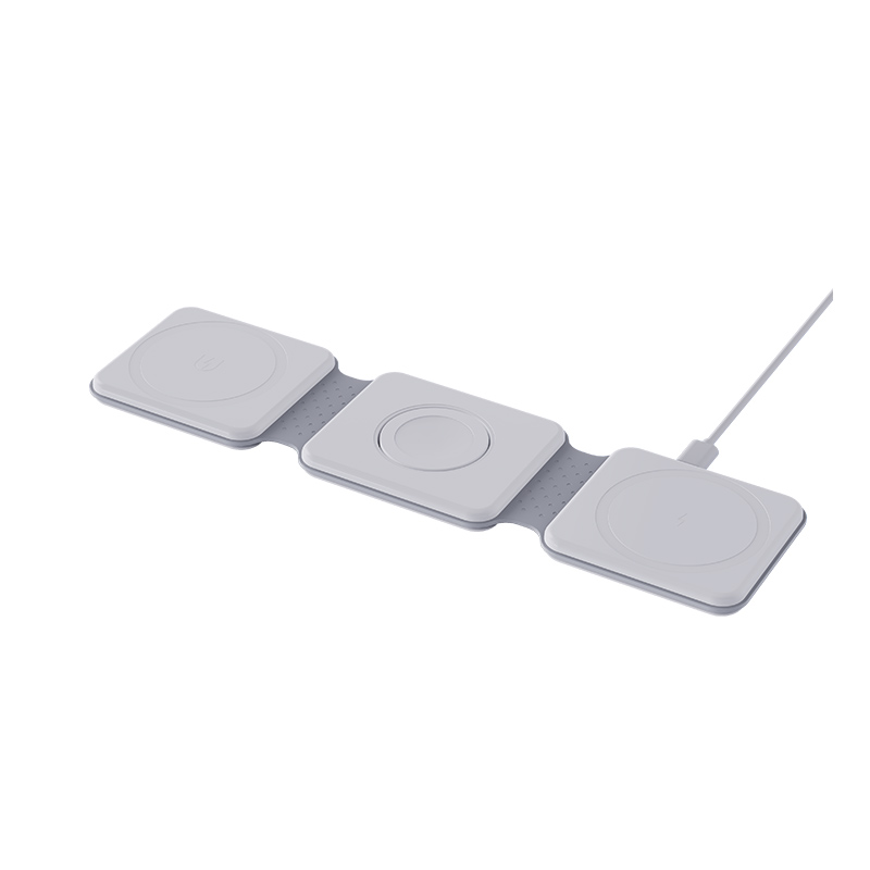
Three costs, and only one of them is the tool.
The tool itself, the cycle time the part takes to mould, and the yield the assembly reaches. The tool is a one-off; the cycle and the yield repeat on every order, which is why a marginally more expensive tool that shortens the cycle usually pays for itself inside a year.
What to review before the die is cut
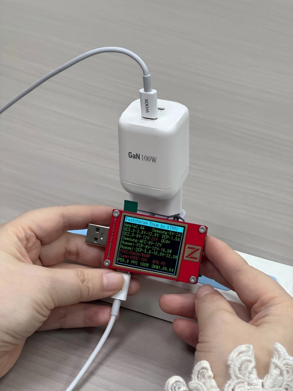
Four items, and the second is the one usually taken on trust.
The part drawings with the wall and draft stated, a moulding simulation or a flow check on the thick sections, the assembly sequence with its tooling, and the test fixture that matches the test points. A review that covers those four closes the gap that produced the enclosure above.
How the four decisions are recorded
The decisions end up in three documents: the part drawings, the process description and the test plan. The drawings carry the wall and the draft, the process description carries the assembly sequence and its tooling, and the test plan carries the points and their limits.
Keeping them at the same revision is what makes a later change visible. A modified clip or a moved probe point changes one of the three, and the other two are reissued with it rather than left describing the earlier design.
The third use is the quotation. A factory asked to quote a change can answer from the documents instead of re-drawing the concept, which is what shortens the second variant of a programme.
A programme holding the three at one revision can move to the next product without repeating the concept work.
FAQ
Does design for manufacturing change the appearance?
It changes the details rather than the design intent. The split line, the draft and the wall uniformity are visible on a finished unit, so they are settled with the industrial design rather than after it. Settle the split line and the draft with the industrial design, because both are visible on the finished unit and both are decided before the die is cut.
Can an existing enclosure be re-tooled for a new platform?
It can, where the thermal and mechanical envelope allows it. The saving is in the tool, and the work moves to confirming that the new board fits the old walls and that the test points still exist. Confirm that the test points still exist in the old walls, because a re-tool that removes probe access turns an inspection into an assumption.
Is a modular architecture always more expensive?
It costs more per unit and less per variant. Where the programme expects several market versions, the connector and the extra board are cheaper than a second enclosure. Compare the connector and the extra board against the cost of a second enclosure, because the second enclosure carries a new die and a new sample cycle. Ask the factory to quote the change from the existing documents rather than from a new concept.
When should the test plan be written?
With the architecture, because it decides the fixtures. A test plan written after the enclosure is released usually asks for a probe point the part does not offer. Write it with the architecture, because the fixtures follow from the test points and a plan written later asks for access the part does not offer. A test plan written later usually asks for a probe point the released part does not offer.
Next step
Send the concept, the variant list and the volume band to Wecent Group through the contact page. The reply covers the architecture, the enclosure, the assembly and the test points before tooling is released. Related reading: OEM and ODM charger manufacturing, GaN charger applications and charger quality control. External references: BSI standards, IEC standards, USB Implementers Forum charger specification, Wireless Power Consortium, UL solutions and TUV testing and certification.
{“@context”:”https://schema.org”,”@type”:”FAQPage”,”mainEntity”:[{“@type”:”Question”,”name”:”Does design for manufacturing change the appearance?”,”acceptedAnswer”:{“@type”:”Answer”,”text”:”It changes the details rather than the design intent. The split line, the draft and the wall uniformity are visible on a finished unit, so they are settled with the industrial design rather than after it.”}},{“@type”:”Question”,”name”:”Can an existing enclosure be re-tooled for a new platform?”,”acceptedAnswer”:{“@type”:”Answer”,”text”:”It can, where the thermal and mechanical envelope allows it. The saving is in the tool, and the work moves to confirming that the new board fits the old walls and that the test points still exist.”}},{“@type”:”Question”,”name”:”Is a modular architecture always more expensive?”,”acceptedAnswer”:{“@type”:”Answer”,”text”:”It costs more per unit and less per variant. Where the programme expects several market versions, the connector and the extra board are cheaper than a second enclosure.”}},{“@type”:”Question”,”name”:”When should the test plan be written?”,”acceptedAnswer”:{“@type”:”Answer”,”text”:”With the architecture, because it decides the fixtures. A test plan written after the enclosure is released usually asks for a probe point the part does not offer.”}}]}