
A safety design is not a list of protection features on a datasheet. It is a set of behaviours that have to work at the boundaries: the current limit that holds during a fault, the temperature threshold that derates before damage, and the behaviour when the input is at the extreme of its range.
Charger safety design: five protections to verify
Over-current, over-voltage, over-temperature and derating, surge and the fault condition, and the behaviour of the construction under each.
Each protection has a trigger, a response and a recovery condition, and each is verified with a measurement rather than asserted from a feature list. The five are ordered by how often they are tested in production rather than only in the laboratory.
Verification is what separates a design from a claim: a protection that has never been triggered on a production unit is a component choice rather than a behaviour.
Check 1: over-current behaviour
The limit, the response and the recovery.
Ask for the current at which the protection engages, what the output does when it engages, and how the product recovers when the fault is removed. On a multi-port product the check also covers the per-port limit and the interaction with the sharing rule. A limit set too high protects nothing; one set too low produces nuisance shutoffs that customers report as a fault.
Check 2: over-voltage behaviour
Two directions: the output and the input.
The output protection protects the device being charged, and the input protection protects the product from a supply that is out of range. Both should state the threshold, the response and the recovery, and both should be verified at the extremes of the operating range rather than at a nominal point. A protection that works at 220 volts and fails at the low end of the input range is a protection with a condition attached.
Check 3: over-temperature and derating
The threshold is a specification item, not an internal detail.
The design has a temperature above which it reduces output, and that threshold with its condition belongs in the datasheet because it is what the customer experiences in a warm room. The verification is a temperature-rise test at full load in the shipping enclosure, at the stated ambient, with the derating point recorded and the recovery behaviour noted.
Check 4: surge and transient behaviour
The event is brief and the damage can be permanent.
Surge protection on the input is shared across all the ports, which is why it is a product-level design item rather than a per-port one. Verification covers the level the design is intended to withstand, the behaviour of the product afterwards, and whether the protection element survives repeated events or requires replacement. The result belongs in the safety evidence with the test conditions stated.
Check 5: the fault condition and the construction
What the product does when a component fails, not only when the load misbehaves.
The construction review covers the isolation barrier, the creepage and clearance distances and the fault conditions the standard requires to be assessed. This check connects the protection behaviour to the physical design: a protection that works electronically while the construction allows a creepage path has not solved the fault condition. The evidence is the construction review with the measurements recorded against each requirement.
| Protection | What to verify | Evidence | Common gap |
|---|---|---|---|
| Over-current | Threshold, response and recovery | Measured trip and recovery | A limit with no recorded response |
| Over-voltage | Output and input directions | Tests at the extremes of the range | Tested at nominal only |
| Over-temperature | The derating threshold and recovery | Rise at full load in the enclosure | The threshold left unstated |
| Surge | The level, the aftermath and the element | The test with its conditions | Protection assumed from the part list |
| Fault and construction | Isolation, clearances and fault conditions | The construction review | Electronic protection without the clearances |
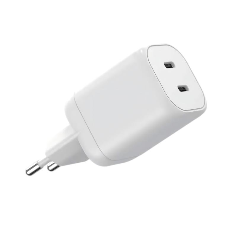
What belongs in production testing
Two protections that are commonly verified on every unit, and three that are not.
The dielectric strength check and the functional verification of the output behaviour are usually performed on every unit. The over-current, over-voltage and surge behaviours are verified on a defined sample or during characterisation, because triggering them on every unit would stress the product. The split belongs in the test plan, with the limits and the frequency stated.

Reading a safety claim
Three questions that establish whether the protections exist as behaviours.
What is the threshold, what is the response, and how was it verified? A supplier that answers all three for a protection is describing a designed behaviour; one that answers with the component name is describing a part list. The distinction matters because the customer experiences the behaviour, and the file has to show it was measured.
FAQ
Is a protection feature list enough for the technical file?
The file needs the thresholds, the responses and the verification for each protection, together with the construction review. A list of features describes the intention rather than the behaviour. The thresholds, the responses and the verification for each protection are what the file needs, because a list of features describes the intention rather than the behaviour, and the behaviour is what the standard assesses.
Should every unit be tested for over-current?
Triggering the protection on every unit stresses the product, so it is normally verified on a defined sample or during characterisation. The dielectric check and the functional output verification are the ones usually performed on every unit. Triggering the protection on every unit stresses the product, while the dielectric check and the functional output verification are the ones usually performed on every unit.
Where does the derating threshold belong?
In the datasheet and the technical file, with its condition: the temperature above which the design reduces output and by how much. It is what the customer experiences in a warm environment. State the temperature above which the design reduces output and by how much, because that condition is what the customer experiences in a warm environment rather than on a bench.
Does the construction matter if the electronics are protected?
It does. Isolation and clearance distances are part of the safety design, and a protection that works electronically does not compensate for a creepage path that should not exist. Isolation and clearance distances are part of the safety design, and a protection that works electronically does not compensate for a creepage path that should not exist in the first place.
Next step
Send the configuration, the output range and the target markets to Wecent Group through the contact page. The reply provides the thresholds and responses for each protection, the construction review position and the split between per-unit and sampled verification. Related reading: GaN charger applications, charger quality control and OEM and ODM charger manufacturing. External references: IEC standards, IEC Webstore, EU Low Voltage Directive, UL standards and certification, TUV testing services and Intertek testing services.
{“@context”:”https://schema.org”,”@type”:”FAQPage”,”mainEntity”:[{“@type”:”Question”,”name”:”Is a protection feature list enough for the technical file?”,”acceptedAnswer”:{“@type”:”Answer”,”text”:”The file needs the thresholds, the responses and the verification for each protection, together with the construction review. A list of features describes the intention rather than the behaviour.”}},{“@type”:”Question”,”name”:”Should every unit be tested for over-current?”,”acceptedAnswer”:{“@type”:”Answer”,”text”:”Triggering the protection on every unit stresses the product, so it is normally verified on a defined sample or during characterisation. The dielectric check and the functional output verification are the ones usually performed on every unit.”}},{“@type”:”Question”,”name”:”Where does the derating threshold belong?”,”acceptedAnswer”:{“@type”:”Answer”,”text”:”In the datasheet and the technical file, with its condition: the temperature above which the design reduces output and by how much. It is what the customer experiences in a warm environment.”}},{“@type”:”Question”,”name”:”Does the construction matter if the electronics are protected?”,”acceptedAnswer”:{“@type”:”Answer”,”text”:”It does. Isolation and clearance distances are part of the safety design, and a protection that works electronically does not compensate for a creepage path that should not exist.”}}]}